
DXT30U(2+2)-F(B) vs Separate Power and Signal Connectors: A Head-to-Head Decision for UAV Wiring
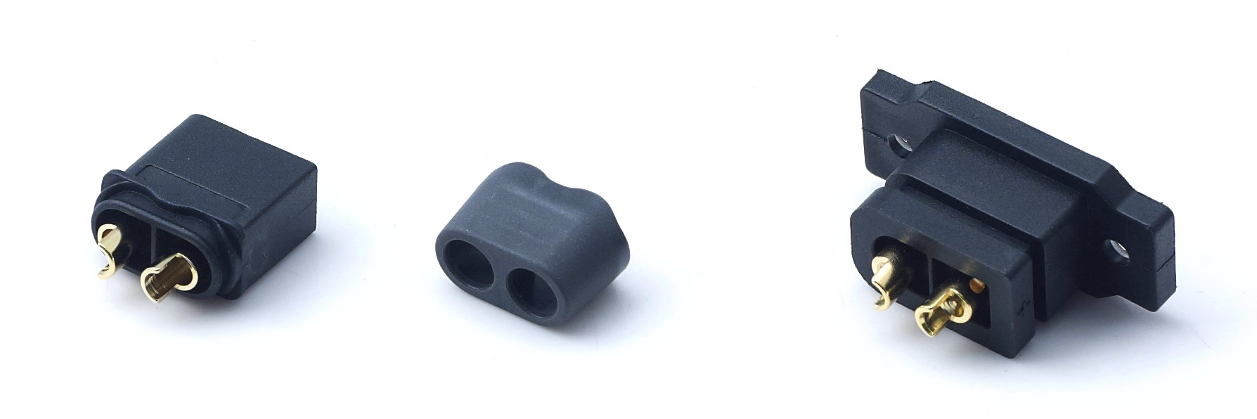
A small UAV battery bay has a fixed amount of volume, a fixed mass budget, and a fixed number of mating operations per flying day. The DXT30U(2+2)-F(B) from AOYG DC Power Connector answers all three at once: it is a cable-soldered female high-current DC power connector that carries two power pins rated 20 A continuous (16 AWG) and two signal pins rated 1 A inside one black PA66 UL94 V-0 housing, with a 35 A peak rating and a rated voltage of DC 500 V. One single mate completes both circuits, so a build no longer needs a standalone power plug plus a standalone signal plug.
That does not make the integrated combo automatically correct for every airframe. The honest answer is conditional: the 2+2 combo wins when weight, packaging space and mating count are the binding constraints, and separate connectors win when the power path must exceed 20 A continuous per pin, when the signal circuit has to be serviced independently, or when the fleet is already standardized on standalone power plugs. This article lays out the comparison on the evidence, not on preference.
Specification Snapshot: What the 2+2 Combo Actually Delivers
Before comparing architectures, it helps to fix the reference part. The DXT30U(2+2)-F(B) belongs to the DXT30U Series of power-signal composite connectors. It is a female, cable-soldered (cable-to-cable) connector with a 2+2 pin configuration, a black housing, and mating counterparts identified as DXT30U(2+2)-M and DXT30U(2+2)P.
| Parameter | DXT30U(2+2)-F(B) |
|---|---|
| Series / gender / termination | DXT30U Series (power-signal composite), female, cable-soldered (cable-to-cable) |
| Pin configuration | 2+2 (2 power pins + 2 signal pins) |
| Housing color | Black (B) |
| Rated voltage | DC 500 V |
| Continuous current | Power pin: 20 A (16 AWG); Signal pin: 1 A |
| Peak current | 35 A |
| Contact resistance | ≤1.2 mΩ |
| Insulation resistance | ≥2000 MΩ |
| Mating cycles | ≥1000 times |
| Protection class | IP40 (IP67 optional for outdoor models) |
| Operating temperature | -20 °C ~ +120 °C |
| Flammability rating | PA66 UL94 V-0 |
| Applicable wire | 12–16 AWG silicone wire |
| Salt spray test | 48 H |
| Mating counterparts | DXT30U(2+2)-M, DXT30U(2+2)P |
The Real Question: Two Circuits in One Housing, or Two Housings?
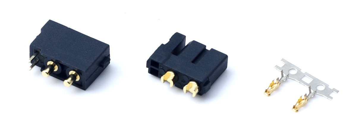
In small UAV, FPV drone and RC hobby builds, the battery-to-ESC power path and the low-current signal path are traditionally kept apart. Power travels through a standalone high-current connector. Telemetry, sensing, BMS communication, gimbal triggering or auxiliary lighting control travels through a separate small signal connector. Two circuits, two housings, two mating actions, two sets of cable retention.
The cost of that separation is not only part count. Every additional connector body adds a solder joint pair, a strain-relief point, a locking feature that can vibrate loose, and one more chance for a hurried battery swap to go wrong. In airframes where every gram and every millimetre is negotiated, two connector bodies also compete for the same real estate as the flight controller stack, the receiver and the battery tray itself.
The counter-argument is equally legitimate and should not be dismissed. Separating the circuits keeps them independent: a damaged signal connector does not force replacement of the power connector, a power connector can be upsized without touching signal wiring, and a pilot already standardized on a common standalone power plug does not want to re-terminate an entire fleet. That is the decision this article resolves.
Industry Background: Why Composite Connectors Are Appearing in Small Airframes
Standalone power connectors have deep ecosystem support. XT60 and XT90 connectors are the primary industry standards for medium to high power non-proprietary RC aircraft and drones in 2026, which means spare parts, adapters and community familiarity all favour them. Any integrated connector enters that environment as an architectural change, not just a component swap.
At the same time, the connector market itself keeps expanding. The global high power connectors market was valued at approximately USD 5.47 billion in 2025 (Fact.MR), and DC connectors represented 58.7% of the energy storage connector market share in 2025 (Dataintelo). Rising DC current density across battery-powered equipment is one driver behind composite, multi-function connector designs that pack more circuits into the same housing wall area.
Alongside market pressure, procurement requirements have hardened. UAV and RC applications commonly specify gold-plated terminals with low contact resistance passing a 48-hour salt spray test, vibration resistance and anti-loosening behaviour, anti-reverse insertion design, UL94 V-0 flame-retardant housings with high-temperature resistance, tolerance of short-time peak current with low temperature rise, compliance with RoHS 2.0 and REACH SVHC, and mating cycles of at least 1000 times. The DXT30U(2+2)-F(B) is designed against that requirement set.
Inside the DXT30U(2+2)-F(B): What the 2+2 Layout Gives You
Two circuits, one mating action
The defining feature is the 2+2 composite pin design. It transmits high-current power and sensing signals simultaneously, which reduces harness quantity and saves internal device space. Practically, this means one connector body, one locking interface and one insertion event instead of two. On a race quad or a compact survey airframe where the battery is swapped several times per session, removing one mating operation per swap removes a whole class of handling errors.
Electrical behaviour on the power and signal paths
Power pins are rated 20 A continuous with a 35 A peak, on 12–16 AWG silicone wire; the signal pins are rated 1 A. Terminals are H62 brass with gold plating, which produces low contact resistance, low temperature rise under high current, and good salt-spray corrosion resistance for stable long-term performance. Contact resistance is specified at ≤1.2 mΩ and insulation resistance at ≥2000 MΩ. Because the signal pins are physically inside the same shell as the power pins, the signal return path travels alongside the power conductors rather than through a separate, often loosely bundled, harness branch.
Housing, temperature and environmental exposure
The housing is PA66 UL94 V-0 flame-retardant plastic in black, rated from -20 °C to +120 °C. That temperature window covers the operating range used across UAV and RC model industry requirements, including high-temperature and low-temperature conditions from -20 °C to +120 °C. Standard protection is IP40, with IP67 optional for outdoor models. For dust-exposed but rain-sheltered installations, IP40 is normally sufficient; for airframes that fly in rain, land in wet grass or operate around agricultural spray, the optional IP67 version is the appropriate configuration. Gold-plated terminals pass a 48-hour salt spray test.
Mechanical security and design flexibility
An anti-misplug structure prevents reverse insertion and the equipment damage that follows a reversed battery connection. Mating life is rated at ≥1000 cycles, which matches the industry requirement for frequently swapped UAV battery packs. The series is compatible with cable-soldered male, vertical-mount PB and horizontal-mount PW PCB male headers, so the same electrical platform can serve a wired harness build or a board-mounted build without changing the mating concept.
Compliance for exported builds
The connector is compliant with RoHS 2.0 and REACH SVHC for global export. For OEM and ODM programmes, AOYG DC Power Connector also supports customized size, current specification, pin position, wiring structure and logo printing, developing and producing exclusive connector products based on the customer's actual application scenario and technical parameters.
Where the integrated combo wins: compact FPV and small UAV airframes, packaging-constrained battery packs, builds where harness mass directly affects flight time, and designs that need power plus sensing in one connector to simplify assembly and battery swap.
Where Separate Power and Signal Connectors Still Make More Sense
An integrated connector is not universally superior, and the cases where separation remains correct are concrete.
- Current demand above the combo rating. The DXT30U(2+2)-F(B) power pins carry 20 A continuous with a 35 A peak. Where a build needs more, higher-capacity standalone power connectors exist in the same supplier family — for example, the DXT90H-M / DXT90S-F UAV connector with a 90 A continuous operating current on 10 AWG, or the DXT60EW-M+DXT60W-F waterproof pair at 60 A continuous and 100 A peak on 8–10 AWG.
- Independent service and repair. If a field repair typically involves only one circuit, keeping power and signal physically separate avoids replacing a whole connector when one path fails.
- Fleet standardization. Operators already running XT60 or XT90 across dozens of airframes inherit adapters, spares and trained handling habits. Introducing a composite interface is a fleet-level decision, not a single-build decision.
- Different environmental grades for each circuit. When the power path must be IP67 for wet conditions but the signal path terminates inside a sealed electronics bay, sealing the two paths to different levels may be simpler as separate parts. The DXT60EW-M+DXT60W-F waterproof pair, for instance, uses a silicone O-ring for IP67 protection and is aimed at waterborne unmanned equipment, outdoor mobile photovoltaic energy storage, marine lithium battery systems and outdoor communication backup power.
- Circuit-level isolation. Where a design wants physical distance between a switching power path and a sensitive low-level signal, one housing forces them into close proximity by definition.
Step-by-Step: How to Choose Between the Combo and Separate Connectors
The sequence below resolves the decision in a fixed order, so that weight or convenience never quietly overrides a current rating.
- Sum the continuous and peak current on the power path. If continuous current stays at or below 20 A per power pin with peaks inside 35 A, the DXT30U(2+2)-F(B) fits. If the pack and ESC pull more, move to a higher-current standalone power connector such as the DXT90H-M / DXT90S-F at 90 A continuous or the DXT60EW-M+DXT60W-F at 60 A continuous / 100 A peak.
- Count the signal lines and their current. Two signal lines at up to 1 A each fit the 2+2 layout. More signal channels, or higher signal current, point toward a separate signal connector or a larger composite series.
- Measure the packaging budget. Compare the volume and mass of one 2+2 housing against the combined volume and mass of a standalone power connector plus a standalone signal connector, including the second strain-relief and the extra harness length needed to route to it.
- Set the environmental grade for the installation. Indoor or sheltered builds can use standard IP40. Airframes exposed to rain, spray or washing should specify IP67 for the power interface. The DXT30U series offers IP40 as standard with IP67 optional for outdoor models.
- Confirm compliance and durability requirements. Check RoHS 2.0 and REACH SVHC compliance, UL94 V-0 flame rating, gold-plated terminals passing a 48-hour salt spray test, and a mating life of at least 1000 cycles.
- Validate on a sample build before committing the fleet. Confirm insertion force, locking behaviour under vibration, temperature rise at your real continuous current, and harness routing inside the actual airframe before changing a production drawing.
Decision rule: if the airframe is packaging-limited and the power path stays within 20 A continuous / 35 A peak, the composite connector removes parts without removing capability. If the power path is the binding constraint, keep the power connector standalone and size it properly.
Use Cases: Where the 2+2 Architecture Fits by Project Type
The DXT30U(2+2)-F(B) is intended for battery pack applications in UAVs, FPV drones, RC hobby models, light-duty e-bikes, portable energy storage, robots, garden power tools, smart devices and BMS systems. Its role is to transmit power between the lithium battery and the ESC, enable quick connection and disconnection of the power supply, keep the model's power output stable, and support simultaneous transmission of power and control signals through a composite connector.
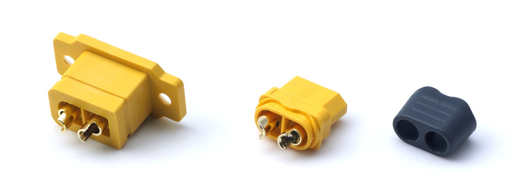
- Consumer FPV racing drones and tiny quadcopters. These are the clearest fit: minimal packaging volume, frequent battery swaps, and a signal path that benefits from sharing the power connector's locking action.
- Aerial photography and light survey UAVs. Where a camera trigger, gimbal communication or sensing line must accompany the battery feed inside a compact frame, one composite connector replaces two.
- Small multi-rotor UAVs and fixed-wing RC aircraft. Standard IP40 protection suits sheltered avionics bays and dust-exposed but rain-sheltered operation, within the -20 °C to +120 °C range.
- Light-duty e-bike and portable energy storage packs. Battery pack and BMS assemblies that need power plus a sensing connection in one interface.
- Service robots, AGV handling robots and garden power tools. Where connector count reduction simplifies harness assembly on a production line.
- Larger UAV and RC projects. Where continuous current exceeds the composite rating, the same supplier family provides standalone power connectors — the DXT90H-M / DXT90S-F at 90 A continuous, the DXT90H-M+DXT90E-F Yellow at 45 A continuous with a 90 A short-term peak for RC cars, RC boats, aircraft models and small UAV lithium batteries, and the IP67 DXT60EW-M+DXT60W-F pair for wet and outdoor duty.
Comparison Table: Integrated Combo vs Separate Connectors
The table below compares the DXT30U(2+2)-F(B) against the alternative of a standalone high-current power connector plus a separate signal connector. Values for standalone AOYG options are listed so the comparison stays on verified figures rather than assumptions.
| Comparison dimension | DXT30U(2+2)-F(B) integrated combo | Separate power connector + separate signal connector |
|---|---|---|
| Mating actions per battery swap | 1 | 2 |
| Connector bodies in the circuit | 1 | 2 |
| Power path rating | 20 A continuous per power pin (16 AWG); 35 A peak; DC 500 V | Selected independently — e.g. DXT30U-M / DXT30U-F: 15 A continuous, 30 A peak; DXT90H-M / DXT90S-F: 90 A continuous; DXT60EW-M+DXT60W-F: 60 A continuous, 100 A peak |
| Signal path | 2 signal pins at 1 A inside the same housing | Carried by a dedicated signal connector |
| Contact resistance | ≤1.2 mΩ | ≤0.7 mΩ (DXT30U-M / DXT30U-F); ≤1.0 mΩ (DXT90H-M+DXT90E-F Yellow); ≤0.8 mΩ (DXT60EW-M+DXT60W-F) |
| Insulation resistance | ≥2000 MΩ | ≥2000 MΩ across listed AOYG standalone options |
| Protection class | IP40 standard; IP67 optional for outdoor models | Depends on selection — IP40 on DXT30U and DXT90H series; IP67 on DXT60EW-M+DXT60W-F |
| Recommended wire | 12–16 AWG silicone wire | 18 AWG (DXT30U); 10 AWG (DXT90H, compatible with 8 AWG); 8–10 AWG (DXT60EW+DXT60W) |
| Mating cycles | ≥1000 times | ≥1000 times |
| Operating temperature | -20 °C ~ +120 °C | -20 °C ~ +120 °C |
| Flammability rating | PA66 UL94 V-0 | UL94 V-0 PA66 across listed AOYG options |
| Salt spray performance | 48 H (gold-plated terminals) | 48 H (gold-plated terminals) |
| Anti-reverse insertion | Anti-misplug structure | Available on standalone connectors by design keying |
| Best fit | Packaging- and mass-constrained small UAV, FPV and RC builds within 20 A continuous / 35 A peak | Higher current demand, independent service of each circuit, or fleet already standardized on standalone power plugs |
FAQ: Choosing Between the Combo and Separate Connectors
1. Is the DXT30U(2+2)-F(B) compliant with RoHS 2.0, REACH SVHC and UL94 V-0 requirements?
Yes. The DXT30U(2+2)-F(B) complies with RoHS 2.0 and REACH SVHC for global export, and its housing uses PA66 UL94 V-0 flame-retardant plastic. Terminals are H62 brass with gold plating and are tested to a 48-hour salt spray condition. These are the compliance points most commonly requested by UAV, RC and lithium battery pack buyers in Europe and North America.
2. What current and voltage can the DXT30U(2+2)-F(B) handle, and is it enough for a small UAV?
The connector is rated DC 500 V, with 20 A continuous on the power pins (16 AWG) and 1 A on the signal pins, plus a 35 A peak current rating. It accepts 12–16 AWG silicone wire. That envelope covers compact FPV drones, small UAVs and RC hobby models that need power plus sensing in one interface. If the build needs more than 20 A continuous, a standalone higher-current connector such as the 90 A DXT90H-M / DXT90S-F or the 60 A / 100 A peak IP67 DXT60EW-M+DXT60W-F pair is the correct choice instead.
3. What does the combo save compared with using separate power and signal connectors?
It reduces harness quantity by combining two circuits into one 2+2 pin layout, saves internal device space, and cuts a battery swap from two mating actions to one. Fewer connector bodies also mean fewer solder joint pairs, fewer strain-relief points and fewer locking features exposed to flight vibration. The trade-off is that the power and signal circuits then share one physical interface, and the power path is bounded by the 20 A continuous / 35 A peak rating.
4. Can the DXT30U(2+2)-F(B) be customized, and what is the minimum order quantity?
AOYG DC Power Connector supports OEM and ODM production, including customized size, current specification, pin position, wiring structure and logo printing, developed against the customer's actual application scenario and technical parameters. The minimum order quantity for connector products is 2 units, which allows a design change to be validated economically before volume release. Monthly production capacity is 8,000 units, with 100% testing.
5. Can I obtain samples, and what is the production lead time?
Sample testing is part of the supplier's one-stop service, alongside product scheme consultation, customized development, mass production and after-sales technical support. The standard lead time is 30–45 days after order confirmation, and products are exported to Europe, America and Southeast Asia. To validate the DXT30U(2+2)-F(B) against your own airframe — insertion force, locking under vibration and temperature rise at your real continuous current — you can request a sample or a quotation through www.aoygvn.com, or contact the team directly at xiuweizhao77@gmail.com / WhatsApp +84 366770891.
About the Supplier Behind the DXT30U(2+2) Series
AOYG DC Power Connector is a manufacturer and solution provider focused on the research, development, production and customization of high-performance high-current DC connection systems for lithium-ion smart devices, operating from a 6,000 m² facility with 100 employees, an annual output of 900,000 units and a 25-engineer R&D team. Founded in 2024, the company holds IATF16949:2016 automotive quality management system certification and applies full-process standardized control from raw material incoming inspection through precision mold development, automated production, finished product testing and factory inspection. Around 50% of output is exported, with main markets in the EU and USA.
Core products comply with international industry safety and environmental protection standards, and the company supports personalized OEM and ODM requirements across commercial and industrial drones, intelligent service robots, garden power tools and portable cleaning equipment. Because the same supplier builds both the composite 2+2 connector and the standalone power connectors described above, the architecture decision stays with the airframe designer rather than being forced by sourcing limitations.
Conclusion: Decide on the Power Path, Then Optimize the Packaging
The DXT30U(2+2)-F(B) is not a replacement for standalone high-current connectors — it is a targeted answer to a specific packaging problem. It carries 20 A continuous per power pin with a 35 A peak and a DC 500 V rating, adds two 1 A signal pins in the same black PA66 UL94 V-0 housing, survives ≥1000 mating cycles, passes a 48-hour salt spray test on gold-plated H62 brass terminals, and complies with RoHS 2.0 and REACH SVHC. Standard IP40 protection, with IP67 optional for outdoor models, covers sheltered avionics bays through to wet-duty installations.
The decision sequence is straightforward. Size the power path first. If it fits inside 20 A continuous and 35 A peak, and the airframe is weight- or space-constrained, the 2+2 combo removes a connector body, a mating action and a strain-relief point without giving up current capability. If the power path is larger, or if the signal circuit must be serviced independently, keep the circuits separate and select a standalone connector sized to the real load — for example the 90 A DXT90H-M / DXT90S-F, the 45 A continuous / 90 A peak DXT90H-M+DXT90E-F Yellow, or the IP67 DXT60EW-M+DXT60W-F pair for wet and outdoor duty.
Ready to test the 2+2 architecture in your own airframe?
AOYG DC Power Connector supplies the DXT30U(2+2)-F(B) composite connector, matching male counterparts (DXT30U(2+2)-M, DXT30U(2+2)P), standalone high-current connectors and custom harness assemblies. Minimum order quantity is 2 units, monthly capacity is 8,000 units, and samples are available for validation.
Request a sample or quotation at www.aoygvn.com · xiuweizhao77@gmail.com · WhatsApp +84 366770891
Reference note: market figures cited in this article are attributed to Fact.MR (global high power connectors market, 2025) and Dataintelo (DC connector share of the energy storage connector market, 2025). Product specifications reflect the published parameters of the AOYG DXT30U(2+2)-F(B), DXT30U-M / DXT30U-F, DXT90H-M / DXT90S-F, DXT90H-M+DXT90E-F Yellow and DXT60EW-M+DXT60W-F connector models.
Have Questions or Need More Details?
Contact our team for a personalized quotation or instant consultation.
Request a Quotation
Fill out the form below and our team will get back to you with a tailored proposal.
WhatsApp Direct Chat
Prefer to chat in real-time? Message us on WhatsApp for instant assistance & quick answers.
- Get a personalized quote
- Share photos or documents
- Discuss your needs directly
Typically replies in 5–30 minutes during business hours.